DiveIno PCB version
In the DiveIno Modules post we reached to that state, where all DiveIno modules have their own fabricated PCB version. If you would like to put all these modules into the Otterbox Pursuit 40 case, you will face with the following problems:
- It is hard to connect all modules to the Arduino Mega board
- It is hard to put all PCBs into the case
It would be much better to reduce the number of connections to the Arduino Mega microcontroller board and host all modules in one PCB.
As you might expect I went back to the original full sized breadboard based DiveIno version, but now I try to squeeze all modules onto a single PCB board.
PCB design
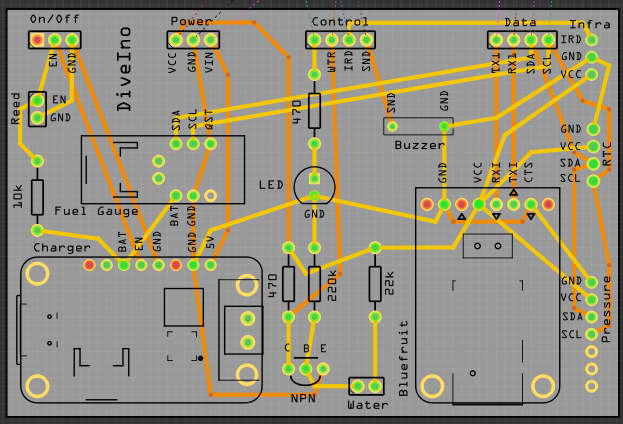
After some hours spent the PCB design looks like this in Fritzing:
PCB fabrication
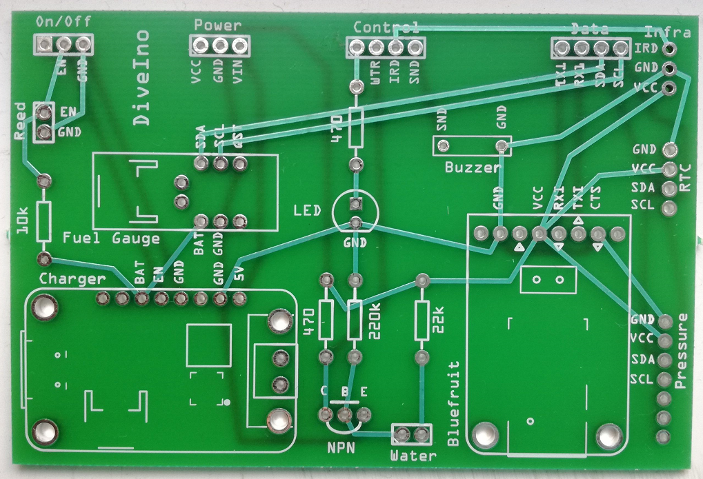
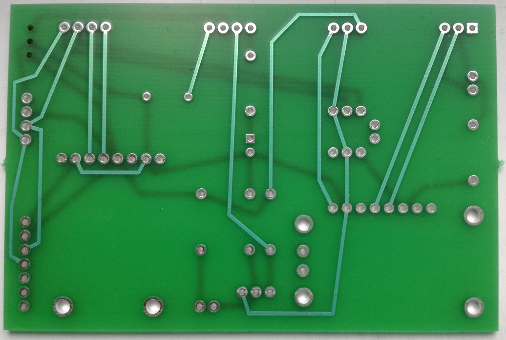
After fabrication the PCB board looks like this:
Solder parts
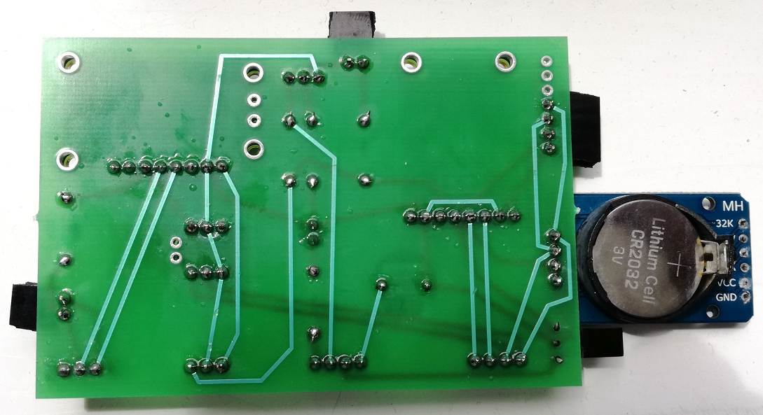
Once the fabricated PCB board is ready, the various DiveIno parts have to be soldered onto the board. The silk screen marks help which part go where.
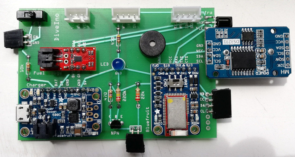
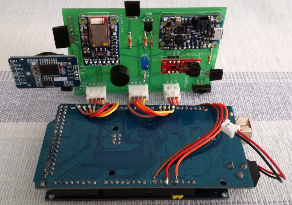
I used JST XH connectors to connect the PCB with the Arduino Mega microcontroller board. Female header connectors provide the connectivity with the followings:
- Pressure sensor
- Water activation wires
- Magnetic on/off switch
The wires from the JST XH connectors were soldered to the backside pins of the Arduino Mega microcontroller board.
PCB test
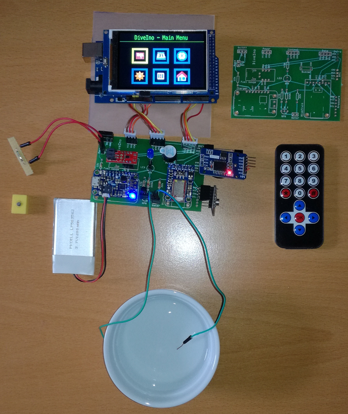
Once the connection has been made with the PCB and the Arduino Mega microcontroller board, it is the time to test the PCB version before the final assembly:
Final assembly
When everything seems to work the only thing left is to put all DiveIno parts into the Otterbox Pursuit 40 case.
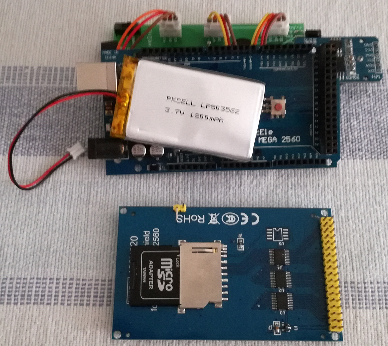
The Lithium Ion Polymer Battery has to be placed between the Arduino Mega microcontroller board and the TFT LCD Displays Module:
The empty Otterbox Pursuit 40 case has wires in the bottom and a separator net in the top section:
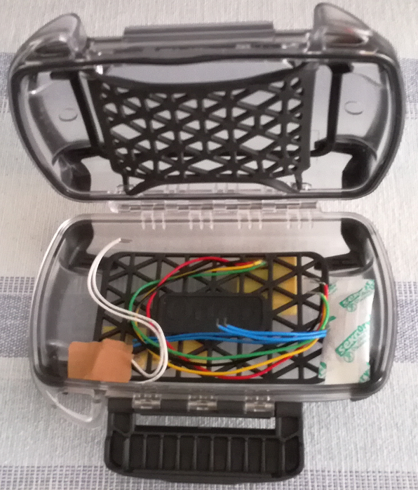
The Arduino Mega microcontroller board will go into the top section hold by the separator net. The PCB board will go into the bottom. Once all the wires are connected, it will look like this:
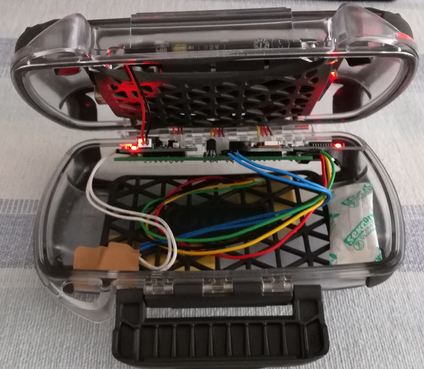
Please note that I inserted a small silica gel bag into the bottom part of the case.
End result
It is a good idea to apply some silicone grease on the sealing rubber ring before the case was closed.
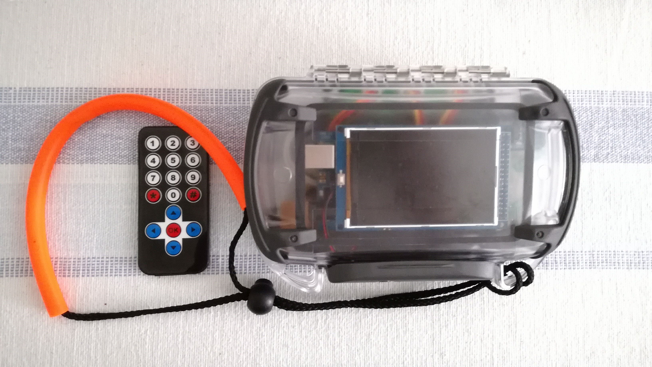
You can also attach a hand strap to prevent its loss during diving.
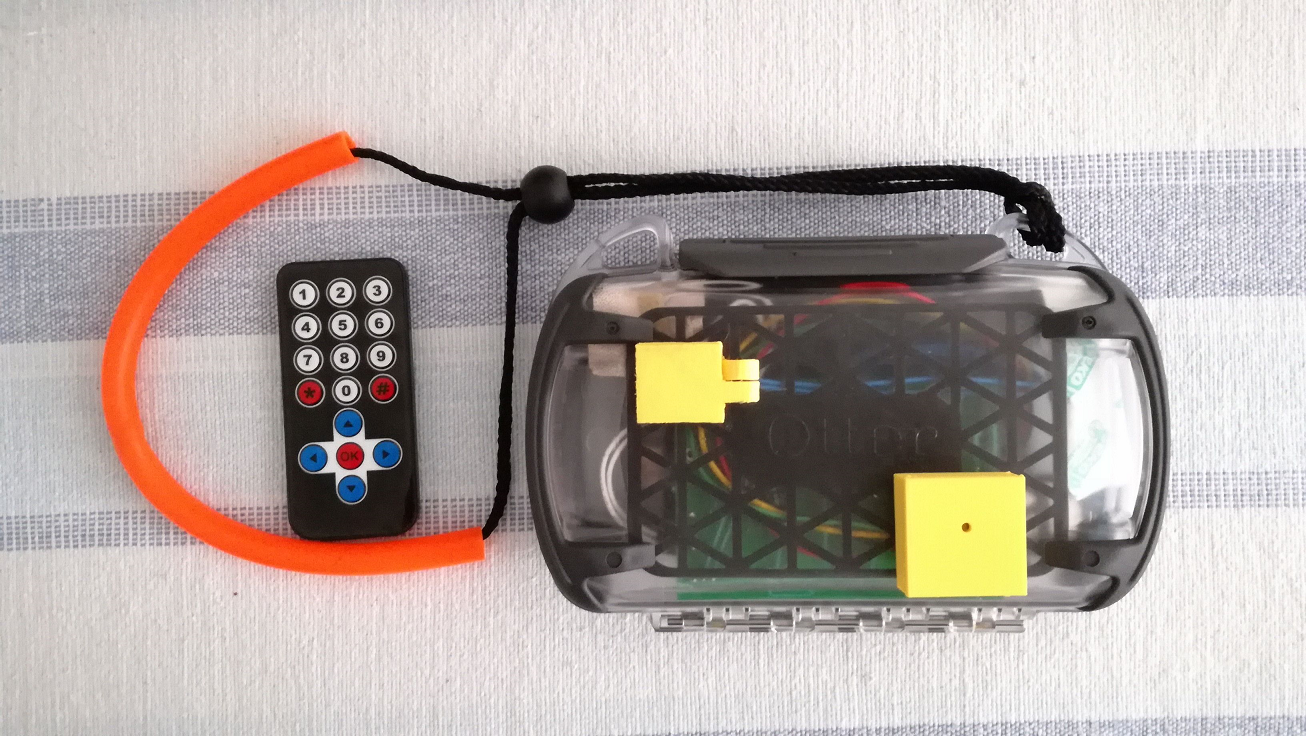
The infrared remote control is also visible on the picture above.
Now DiveIno PCB version is ready for diving!

