DiveIno Modules
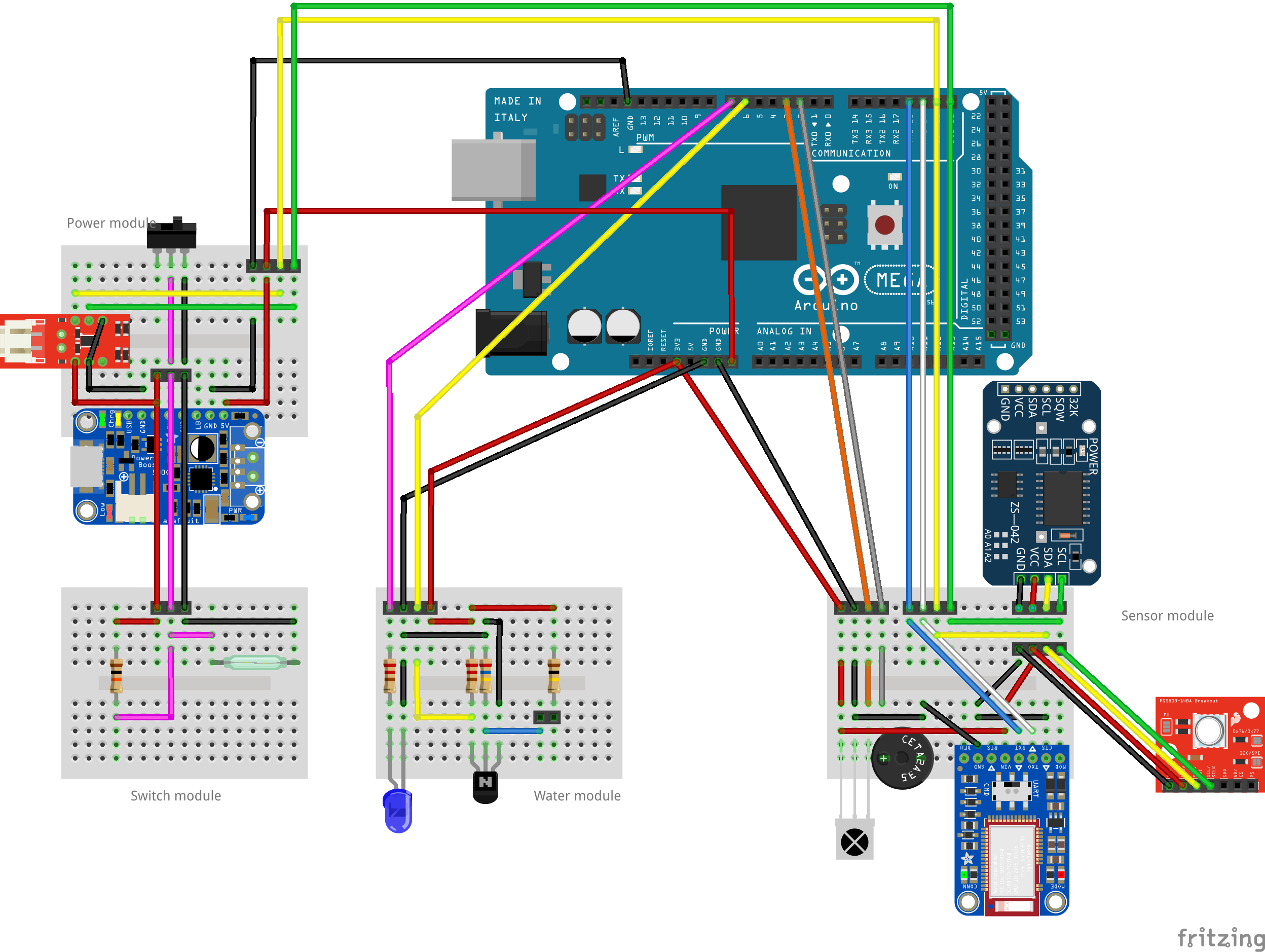
In the Fritzing post I mentioned that the drawback of the full breadboard view is that it can’t be squeezed into the Otterbox Pursuit 40 watertight case. The solution for this problem was to break up the components into functional modules.
Modules
As a reminder DiveIno is built up from the following modules:
- Power Module - these parts provide the power to DiveIno
- Switch Module - can turn on and off DiveIno
- Water Module - be able to detect, if DiveIno is in the water
- Sensor Module - provides time, pressure and Bluetooth communication capabilities

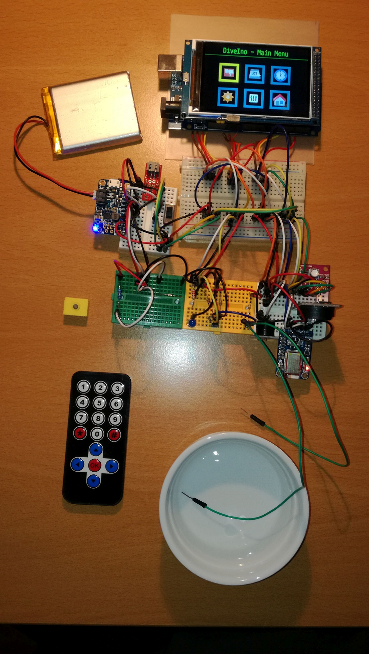
Breadboard view
These modules not only separate the parts based on their functionality, but can be easily fitted onto a mini solderless breadboard:

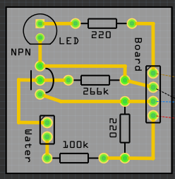
PCB view
Once DiveIno works correctly these mini solderless breadboards can be further miniaturized on a real printed Printed Circuit Board (PCB). The Modules folder on GitHub contains the Fritzing diagrams for all modules. The PCB view contains the PCB schematics of each modules:

A good overview article about PCB design can be found on the Sparkfun website called PCB Basics.
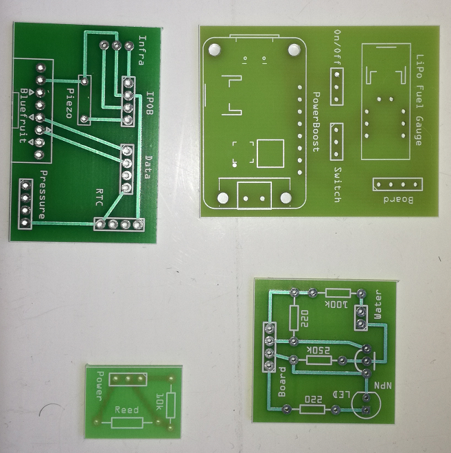
PCB fabrication
These PCB schematics can be exported to Gerber files. The files can be sent to PCB fabrication houses - companies that turn the PCB design into real boards - to get printed. Actually Fritzing offers fabrication right from its tool, which makes it another viable option.

Test the PCB board
The last step to make DiveIno work on a modular PCB board is to solder all parts onto the board. The end result will look like this:

If you would like to reuse the expensive electronic parts later, solder female pin headers onto the PCB. The male headers can nicely fit right into the female headers.

