DiveIno Arduino Shield version
DiveIno PCB version is cool! It helps to get rid of messy wiring, but has different problems on the hardware side. First of all the board connection wires have to be soldered onto the bottom of the microcontroller board, which makes it hard to assemble and disassemble the computer.
The other big issue is that the TFT LCD Display Module only fits on top of the Arduino Mega 2560 board without any issues. In case of an Arduino Due board, the SD card reader doesn’t work. This is a problem, because Arduino Due offers better speed for DiveIno, which means prompt menu item transition and display of every elapsed second in dive mode.
I wanted to address these problems with an Arduino Shield design, which can be plugged easily between the microcontroller board and the TFT LCD Display Module. I designed a series of shields - called revisions, which can be seen on the photos below:


The PCB design of these shields can be found inside the /Fritzing/Shield folder on GitHub. It is easy to get it fabricated from the corresponding Fritzing diagram.
Revision One
The first revision supports only Arduino Mega 2560. It can be considered as a one to one replacement of the DiveIno PCB version.
As it can be seen on the photo below all DiveIno parts were soldered onto the PCB. The TSOP38238 IR Receiver Sensor has to be soldered from the top.
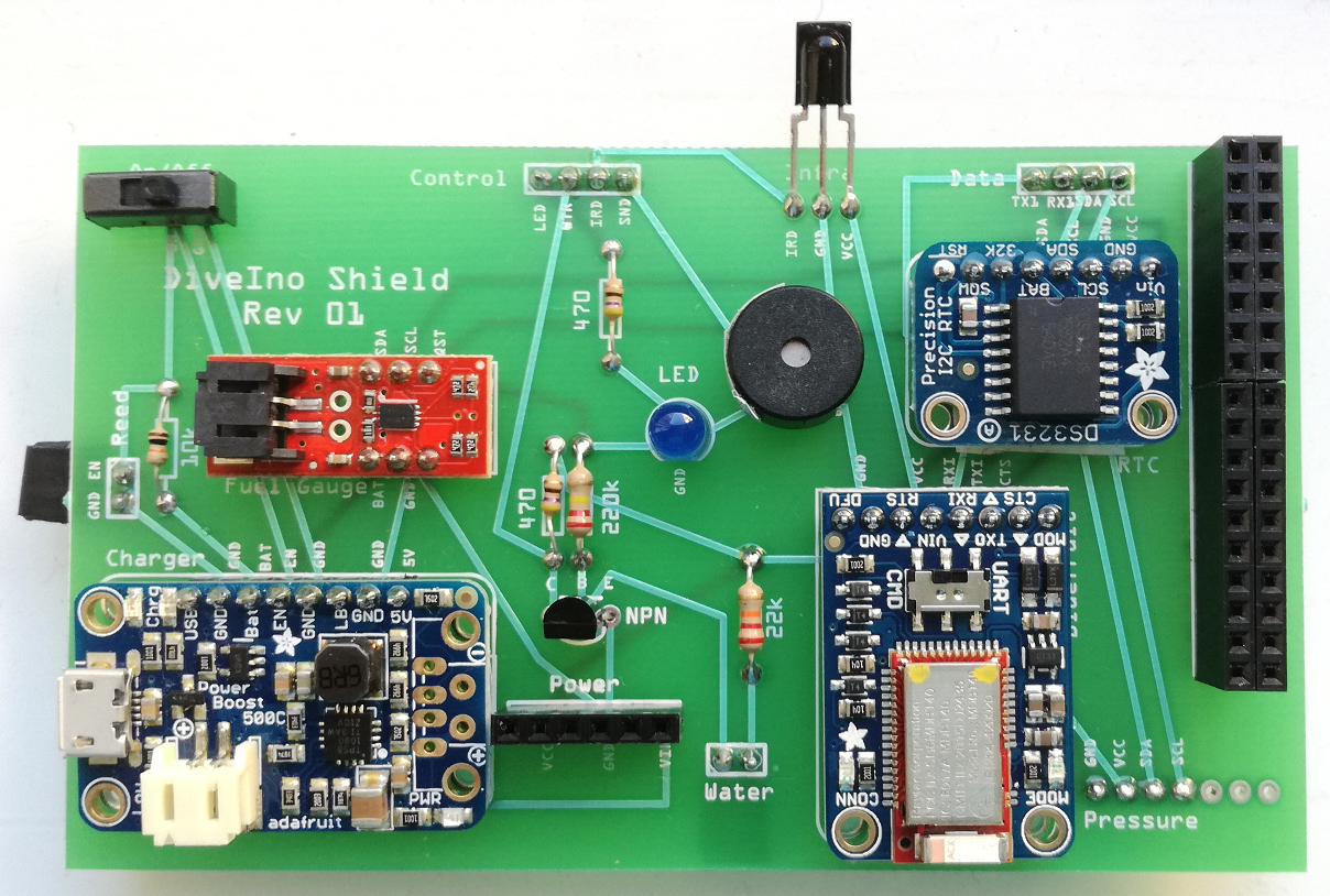
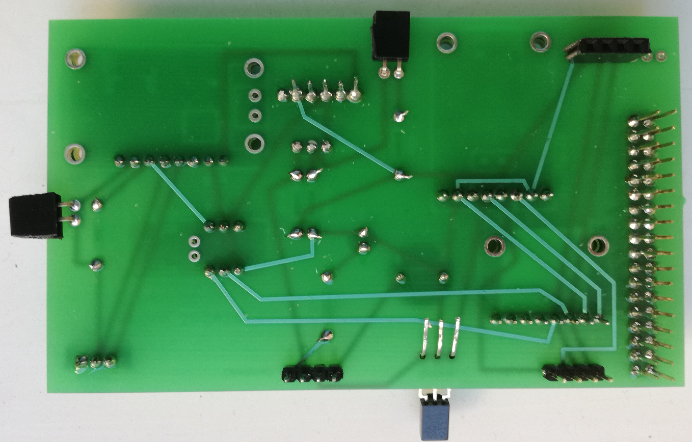
I used Arduino Stacking Headers for the TFT LCD module and Power connections. The Control and Data connections were created by standard Male Headers.
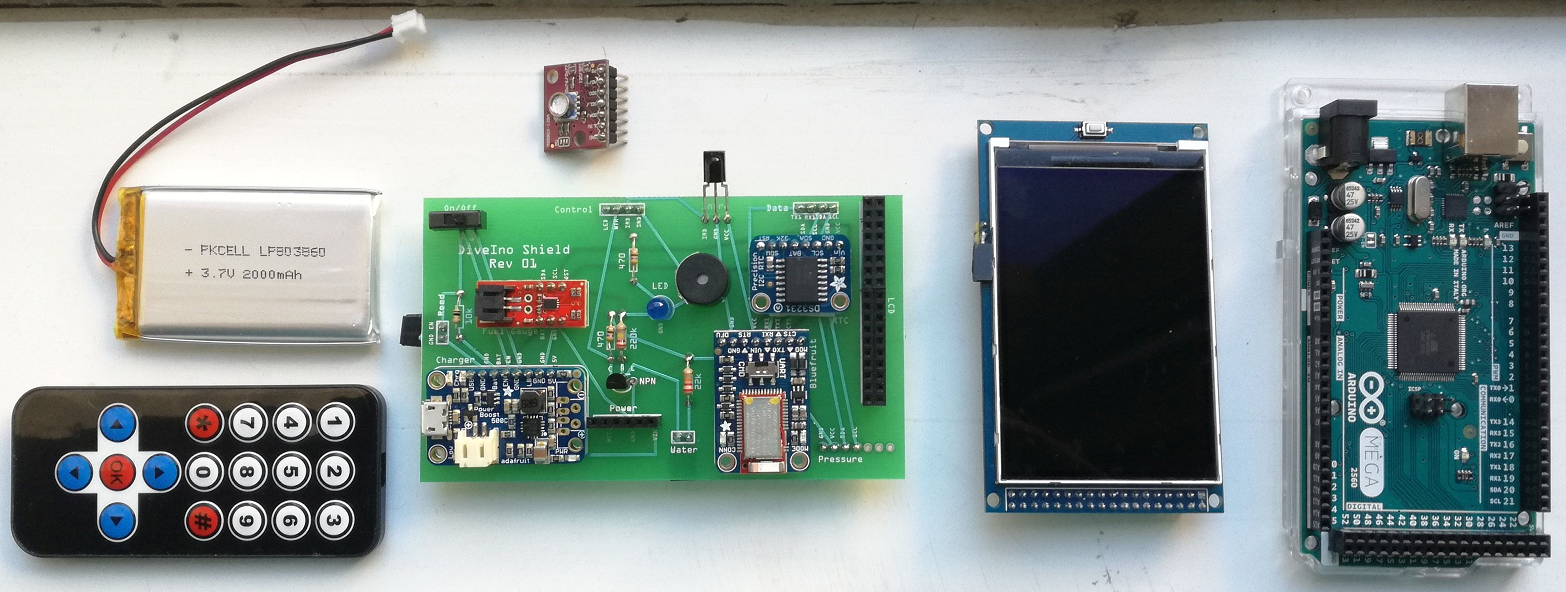
Besides the assembled shield, a full DiveIno dive computer has the following additional components:
- Arduino Mega 2560 board
- TFT LCD Display Module with an SD card slot
- MS5803-14BA Pressure Sensor Breakout
- Lithium Ion Polymer Battery - 3.7v 1200mAh
- Mini Remote Control
It is quite easy to put every component together to form the first revision of DiveIno Arduino shield version:
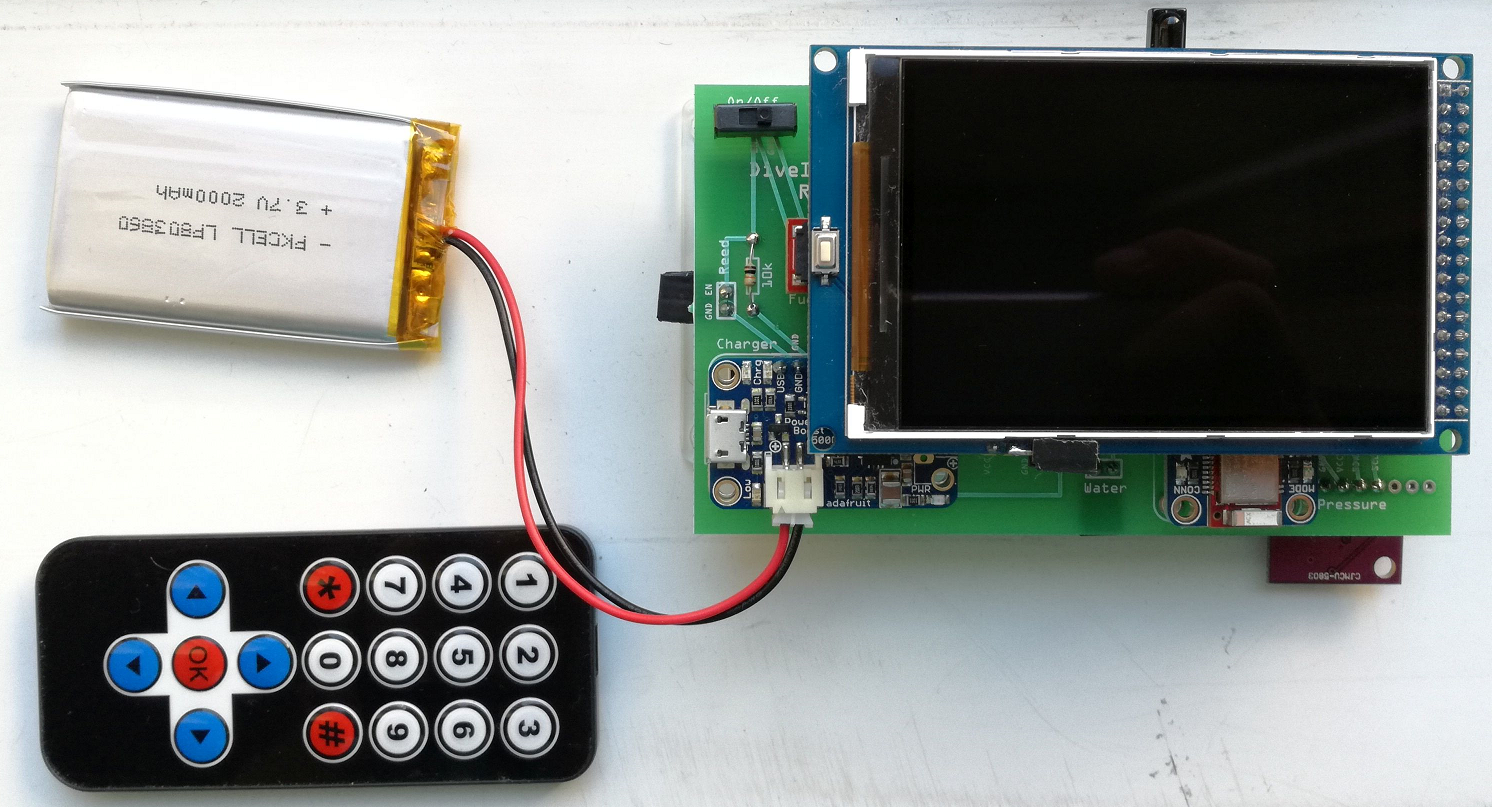
This setup works like the DiveIno PCB version, but it has got several problems:
- No Arduino Due support
- Uses rare and expensive Arduino Stacking Headers
- The Arduino Stacking Header pins are quite thin, which means intermittent electrical connections
Revision Two
This revision tries to replace the Arduino Stacking Header pins with standard Male and Female headers. These can be bought in any electrical parts shop. The Data and the LCD-Power uses standard Female headers. On the back - board - side of the PCB Male headers can be found.
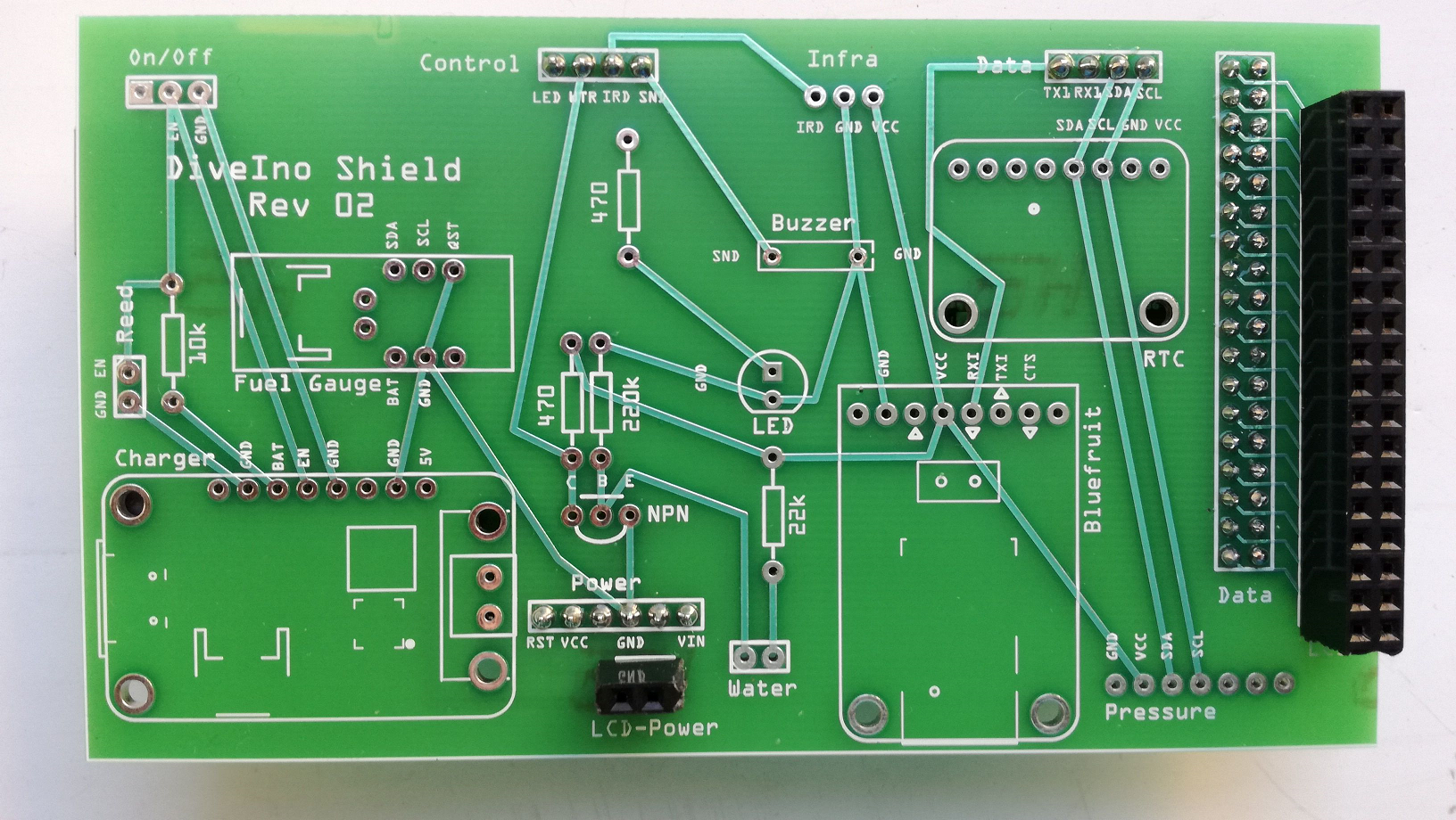
I used this revision only to test the replacement concept described before, so the other DiveIno parts are not soldered onto the PCB.
Revision Three
This revision contains other improvements. It supports Arduino Due! The problem was that on Arduino Due, the SPI interface pins are moved into the central part of the board. The SD card slot on the
TFT LCD Display Module uses SPI as a communication protocol, so the module and the board pins have to be connected with each other. This means that some additional Female headers have to be soldered onto the shield to make this connection possible.
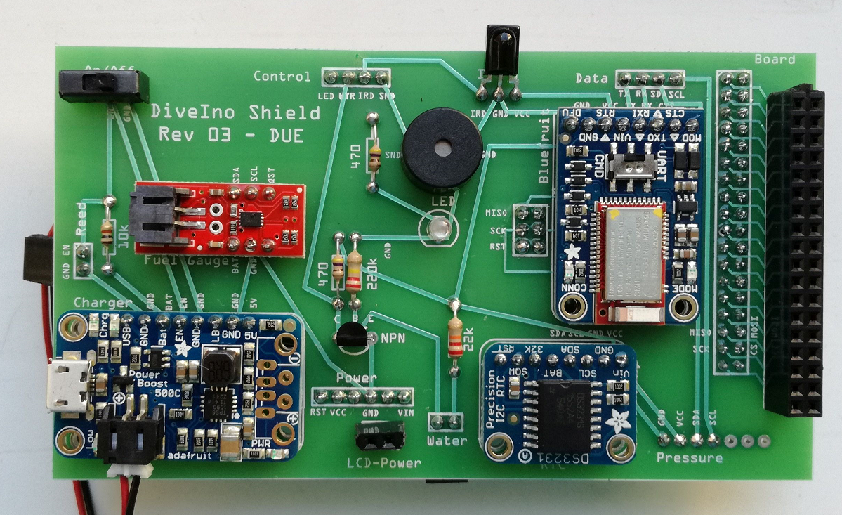
The other improvement was that I switched the location of the DS3231 Precision RTC Breakout with the Bluefruit LE UART Friend module. This means that it is possible now to replace the battery in the RTC breakout board without desoldering the parts from the PCB.
Now the shield can be plugged onto the Arduino Due board without any issue.
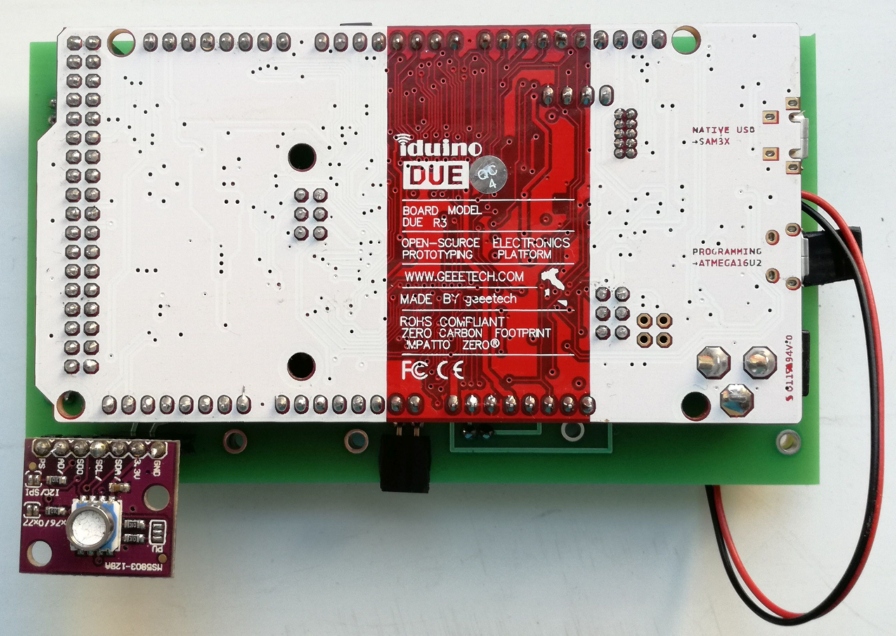
The Lithium Ion Polymer 1200mAh Battery can be placed between the shield and the Arduino Due microcontroller board with bending some pins as it can be seen on the picture below:
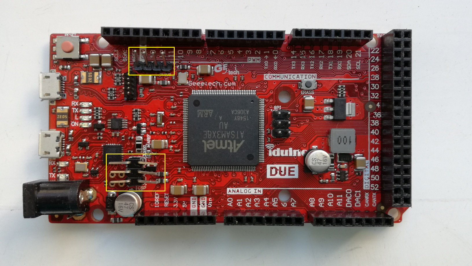
The final assembled version looks like this:
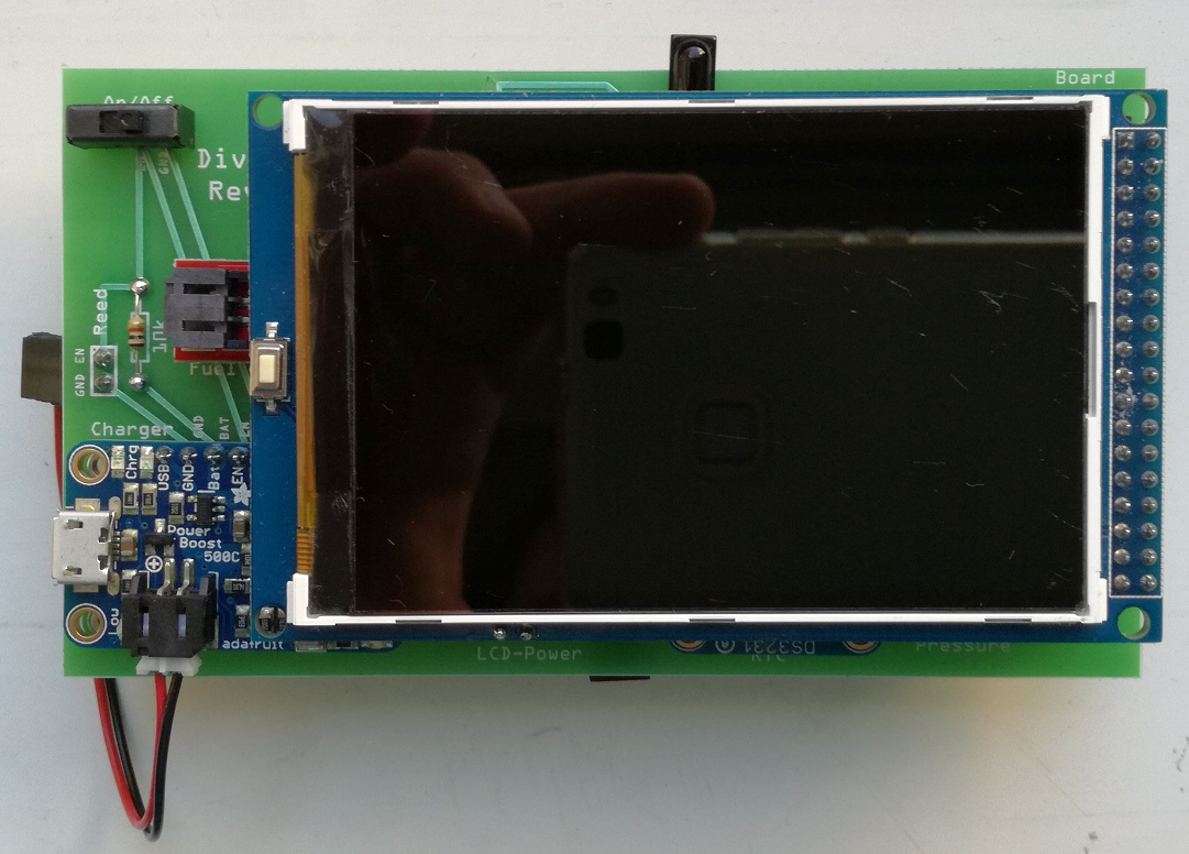
This can go into the case, which is the same as used for the DiveIno PCB version.

