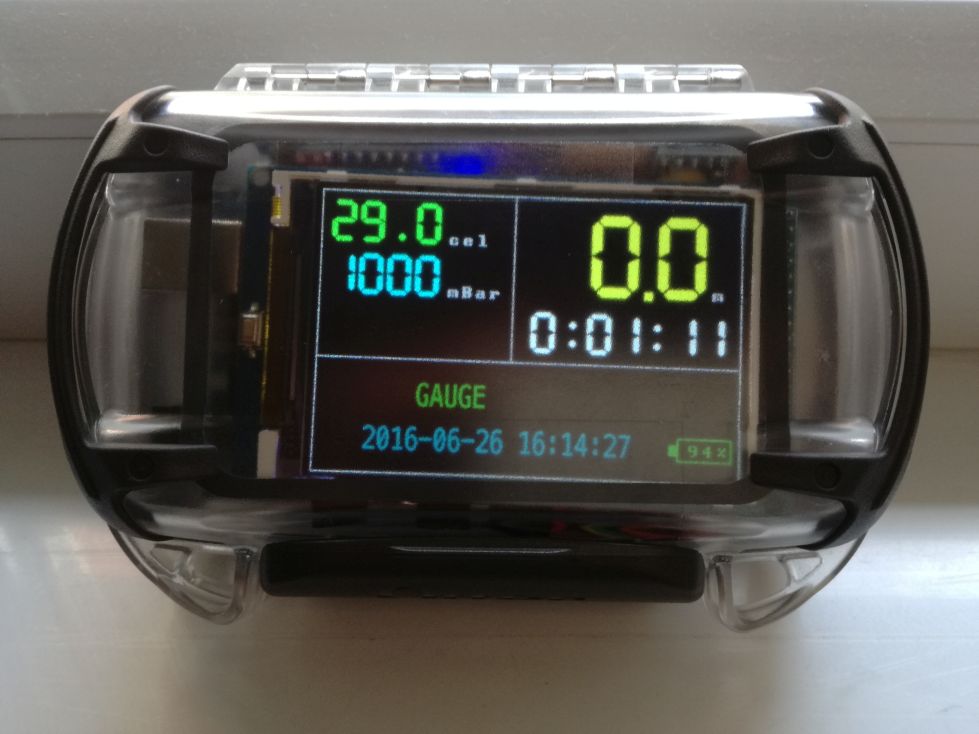
The Long Board version
As I wrote in the Failure during the test dive post I totally destroyed my Otterbox Pursuit 40 case based DiveIno during the first test dive. I promised all of you that I won’t give up the project and rebuild DiveIno from the ashes.
During this week I will have an opportunity to do another test dive in Croatia, so if I don’t want to miss it out than I have to build something quickly. The only “minor” problem is that my newly purchased Otterbox Pursuit 40 case will arrive from the USA next week!
Fortunately previously I ordered the smaller Otterbox Pursuit 20 case. You can read a comparison about the two different versions here. Originally I decided to use the bigger one, because the parts fit more comfortably into it. The smaller seemed to be too tight for the Arduino Mega board, the LiPo battery, the Sensor module and the Power module. Now because I have no other option I have to try and fit everything into this smaller case!
The birth of the Long Board
Once I put my spare Arduino Mega 2560 R3 Module + 3.2 inch TFT IPS LCD Kit into the case, it became clear that some very limited space remained below and next to the board itself. I had to use this space, so the idea was to put all DiveIno components onto a Stripboard with continuous strips and place it right next to the Arduino Mega board. The LiPo battery can go under the board just beside the pressure sensor connector.
I had no space to keep the Sensor module and Power module separated from each other. Everything has to be placed onto the same stripboard.
I also wanted to keep the necessity of disassembly at the minimum, so it would be a great thing that LiPo battery charge can be done through the board itself. Thankfully this problem was solved previously during the Charger module design!
Based on all of these requirements Long Board was born as a mashup of the Sensor module and the Charger module! As you might figured it out the name comes from the shape of the module.
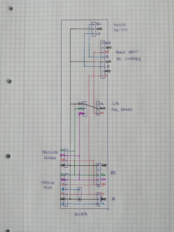
Required parts
| Supplier | Part | Price |
|---|---|---|
| Ebay | CJMCU MS5803 14BA Pressure Sensor Module | $28,55 |
| Ebay | Otterbox Pursuit 20 clear case | $18,00 |
| Sparkfun | LiPo Fuel Gauge | $9,95 |
| Adafruit | TSOP38238 IR Sensor | $1,95 |
| Adafruit | PowerBoost 500 Charger | $14.95 |
| Adafruit | Lithium Ion Polymer Battery - 3.7v 2500mAh | $14,95 |
| Adafruit | Hook-up Wire Spool Set | $15,95 |
| Deal Extreme | Arduino Mega 2560 R3 Module + 3.2 inch TFT IPS LCD Kit | $19,51 |
| Deal Extreme | DS3231 RTC Module | $2,66 |
| Deal Extreme | 17-Key IR Remote Control | $3,30 |
| Deal Extreme | Kingston SDC4/8GB Memory Card with Adapter | $3,98 |
| Deal Extreme | Breadboard Jumper Wires | $2,91 |
| Deal Extreme | Straight Male Headers | $2,70 |
| Deal Extreme | Straight Female Headers | $3,06 |
| Hestore | 20mm Piezo Transducer Sound Disc | $0,2 |
| Hestore | Stripboard - Continuous strips | $0,6 |
| Hestore | SPDT Slide Switch | $0.6 |
Compared to the original Expected cost list the DC-DC Converter Booster Module was replaced with the PowerBoost 500 Charger module. The same applies to the SPDT Slide Switch and to the 20mm Piezo Transducer Sound Disc.
If you sum up everything, the price will be around $144, which is still pretty good for a DIY dive computer!
Solder all parts to the stripboard
I suggest to start soldering from the top of the board. Once all connections are made then place the remaining parts onto the board.
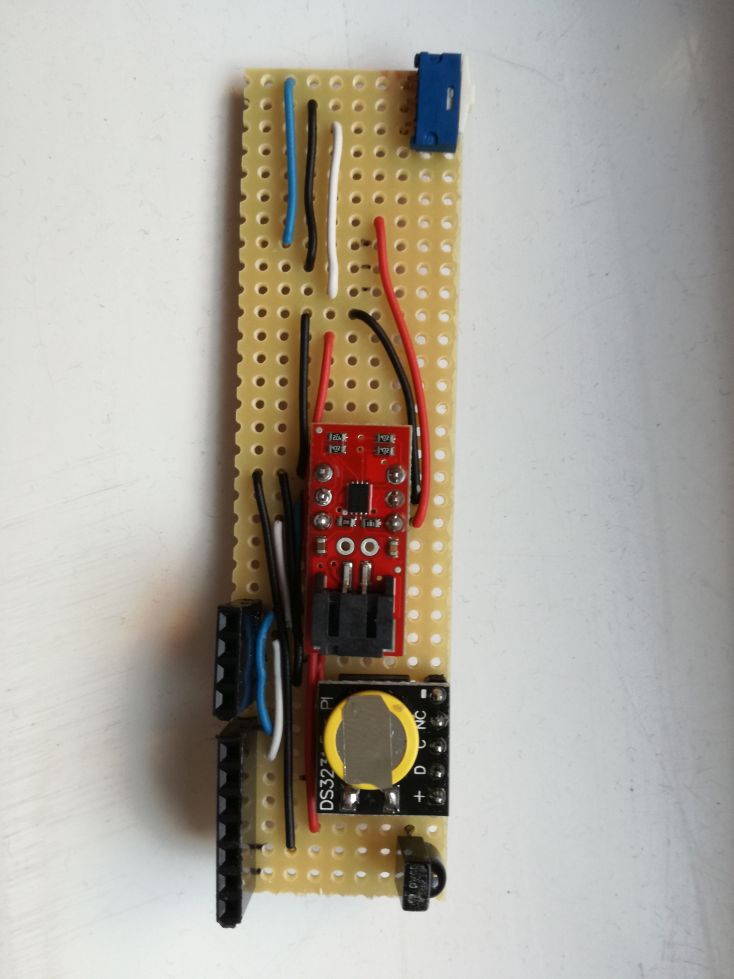
As you might notice that I replaced the original Female Headers of the DS3231 RTC Module with Male Headers. It was required because of space limitations.
Do not forget to break the connection between the two header pin sides of the LiPo Fuel Gauge!
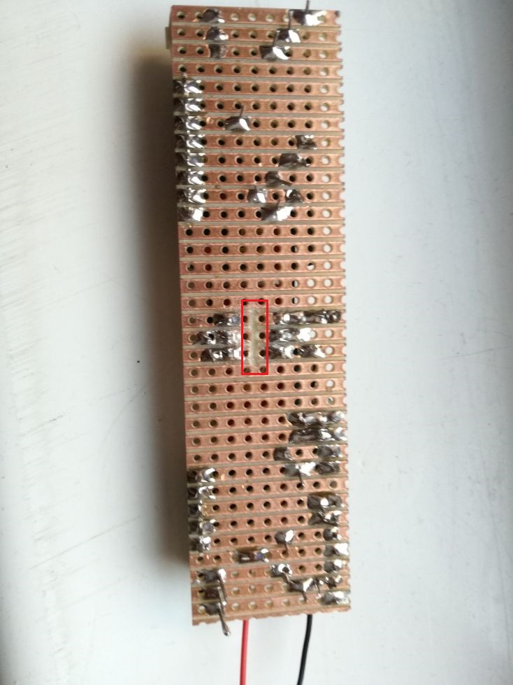
It is also a good idea to cover the back side of the stripboard with Electrical Insulation Adhesive Tape.
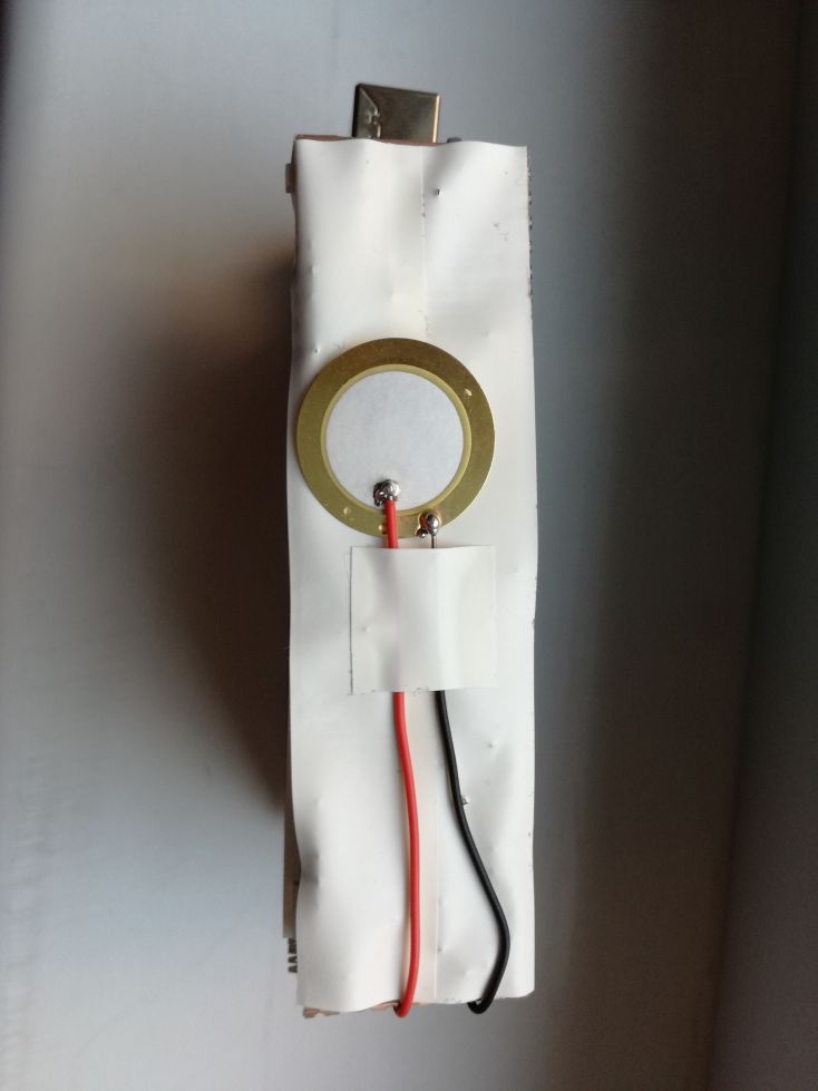
Now the fully assembled Long Board can be connected to Arduino Mega 2560 with Breadboard Jumper Wires.
Modify the case
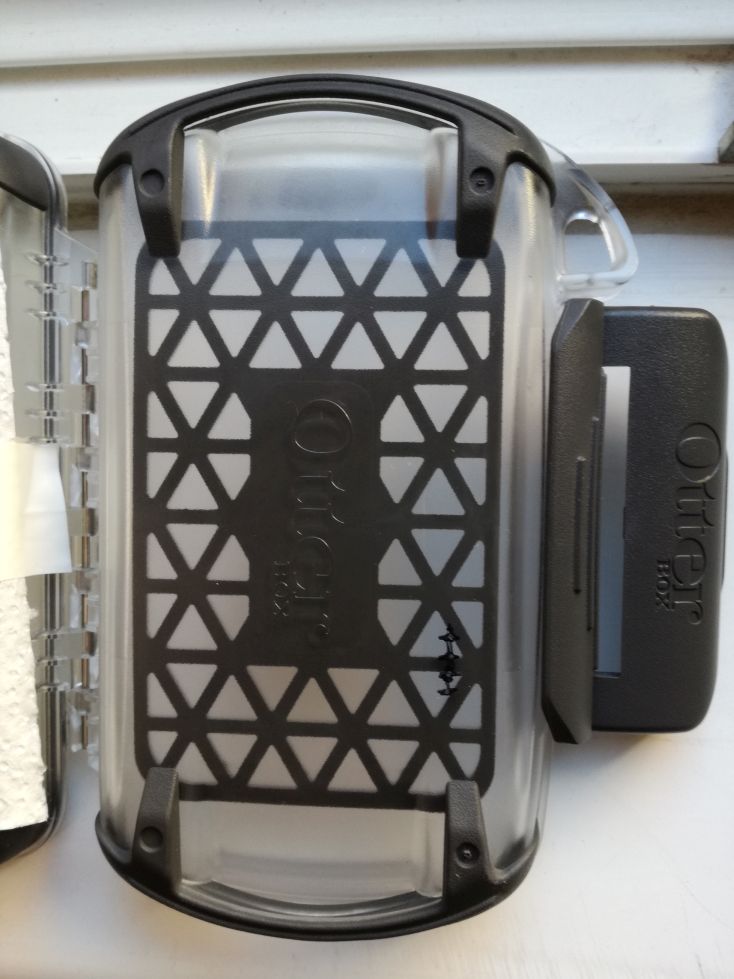
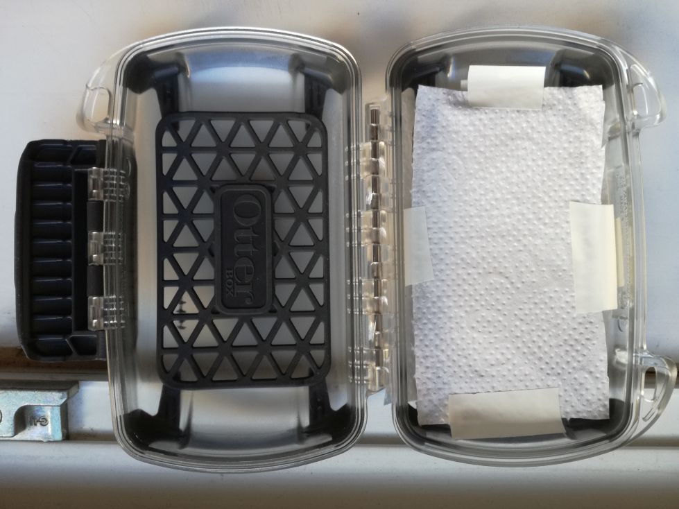
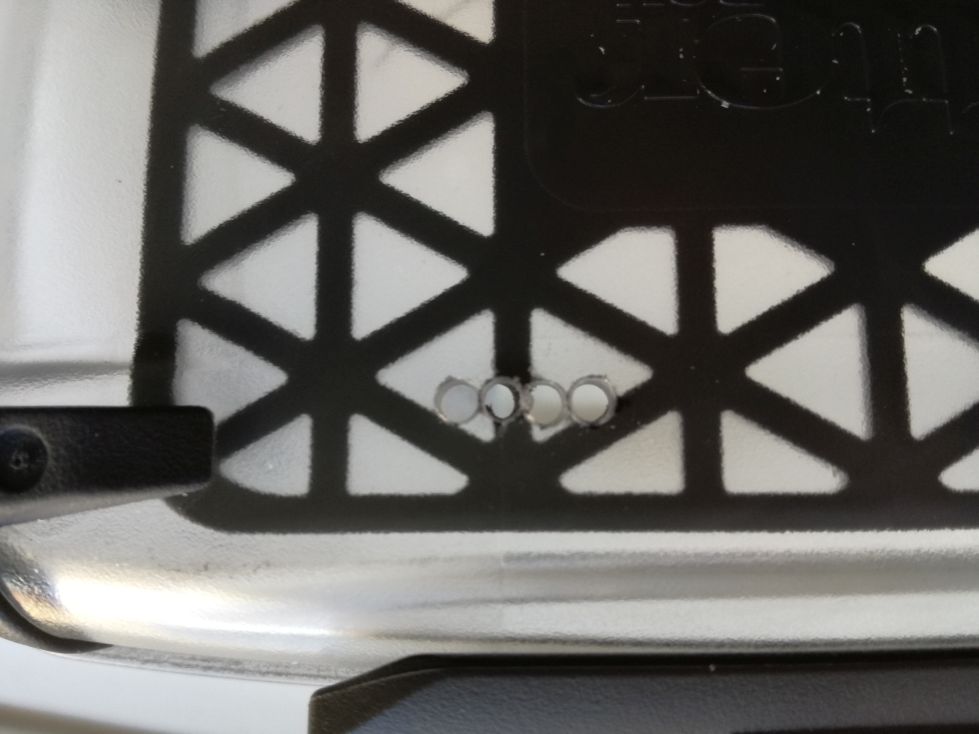
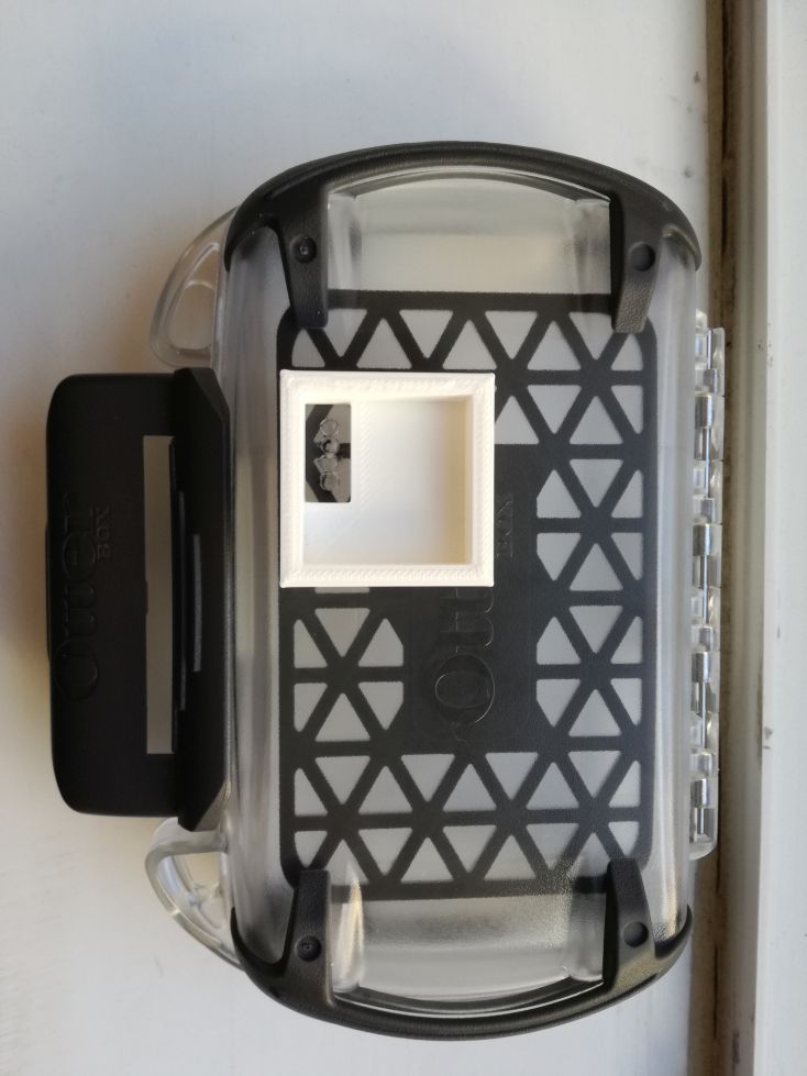
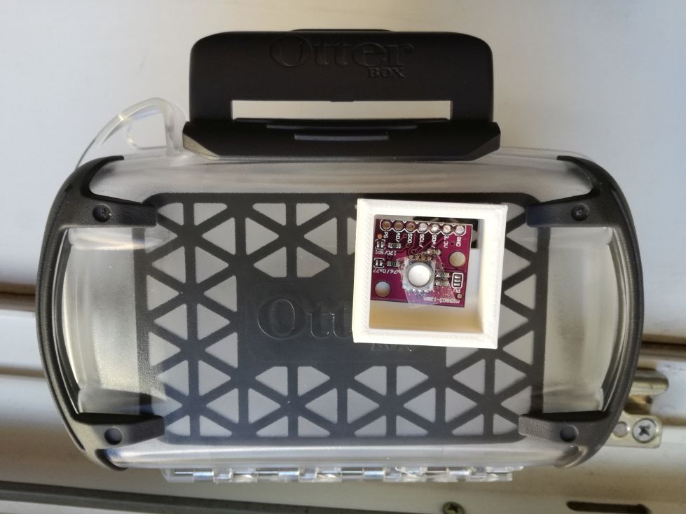
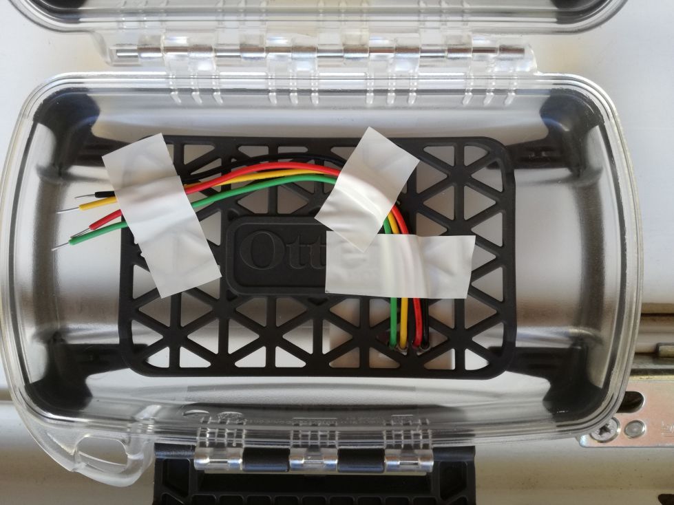
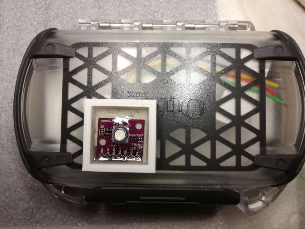
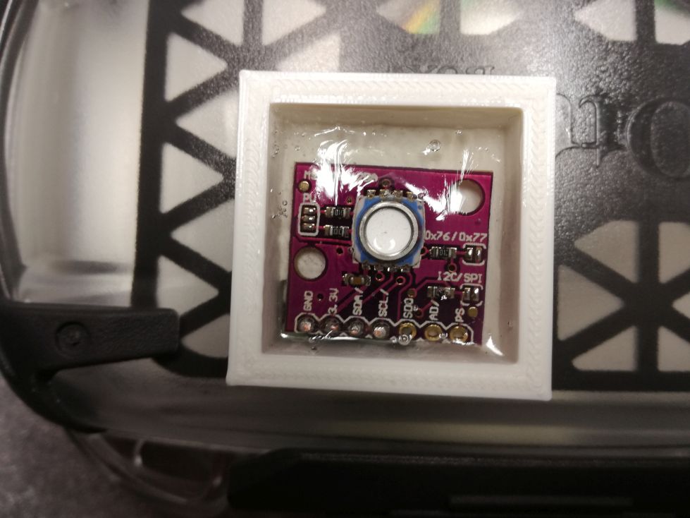
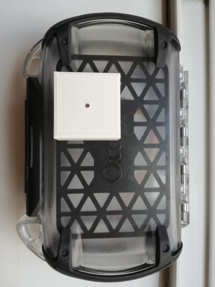
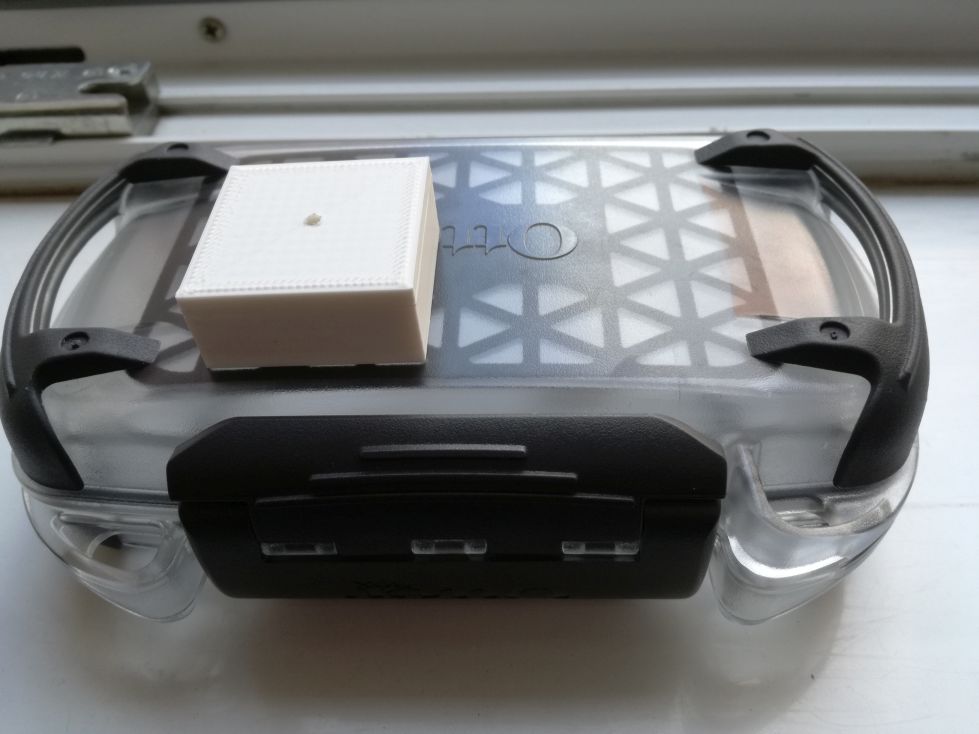
The CJMCU MS5803 14BA Pressure Sensor Module has to be placed on top of the Otterbox Pursuit 20 case just as it was explained in the Assembly - Watertight case post.
The following pictures illustrate the assembly process:
Test your work
Once the case assembly was done, attach the LiPo battery to the PowerBoost 500 Charger module and plug in the pressure sensor wires into the Long Board based socket.
If DiveIno gets turned on, the Gauge Screen should look similar like this:
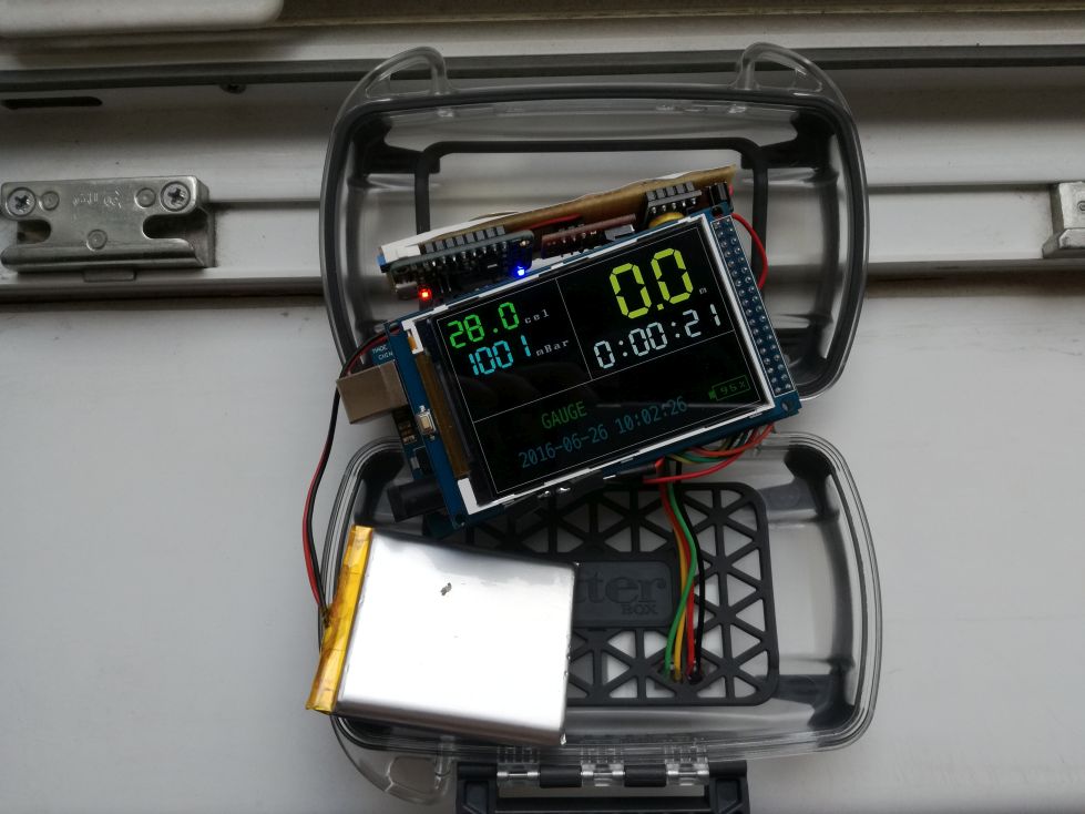
If everything seems to be fine, the case can be closed and your newly assembled DiveIno is ready for a test dive:
