Assembly - Screen and microcontroller module
In the DiveIno parts post I mentioned that DiveIno has the following three modules:
- Screen and microcontroller
- Sensor module
- Power module
In this post I would like to show how the Screen and microcontroller module can be assembled.
Parts
You will need the followings:
- Arduino Mega 2560 R3 Module + 3.2 inch TFT IPS LCD Kit
- Kingston SDC4/8GB Memory Card with Adapter
- Breadboard Jumper Wires

Screen
The TFT LCD screen fits perfectly on top of the Arduino Mega microcontroller board. Just before you plug the screen into the board pins, the followings have to be done:
- Format the SD card to FAT16 file system - most of the SD cards are formatted like this by default
- Make sure that the SD card is empty
- Plug the SD card into the SD card slot of the LCD screen
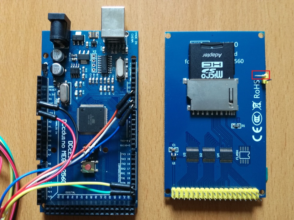
- Bend the RESET pin with 90 degrees
The last step prevents the operation of the RESET button on top of the LCD screen board. It is marked with red on the previous picture. This step is required because if the module is in the waterproof case, the increasing pressure can hit the RESET button and your DiveIno will reset itself under the water!
In order to be able to power the other modules we need 3.3V. Right beside the RESET pin there is a 3.3V pin, which plugs into the 3.3V slot of the Arduino Mega board once it gets fully assembled.
In order to be able to connect the 3.3V power slot with the other modules, you have to solder a female header to the top side of the LCD screen board just like as it can be seen on the picture below:

Please plug in a red jumper wire into the female header slot!
Arduino Mega microcontroller board
You need some jumper wires and bend the pins in 90 degrees. You have to plug in these pins into the following slots:
- Black wire to the GND slot
- Red wire to the VIN slot - to power the microcontroller
- Orange wire to the digital 11 slot - to communicate with the Infrared Receiver
- White wire to the digital 9 slot - to receive LiPo battery alarms
- Blue wire to the digital 8 slot - to drive the buzzer
- Yellow wire to the SDA slot - required for I2C communication
- Green wire to the SCL slot - required for I2C communication
Assemble it together
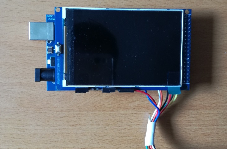
Once you are done with these connections, place the LCD screen module on top of the Arduino Mega microcontroller board. The end result should look like this:

Maybe it is a good idea to tape the wires together, before the connection has been made between the this and the Sensor module.

