Fritzing diagrams
Usually DiveIno assembly starts on the breadboard. You ordered the required parts and now you would like to make sure that each and every part works together. In this test step a wiring diagram becomes quite handy.
Such diagrams can be created in Fritzing.
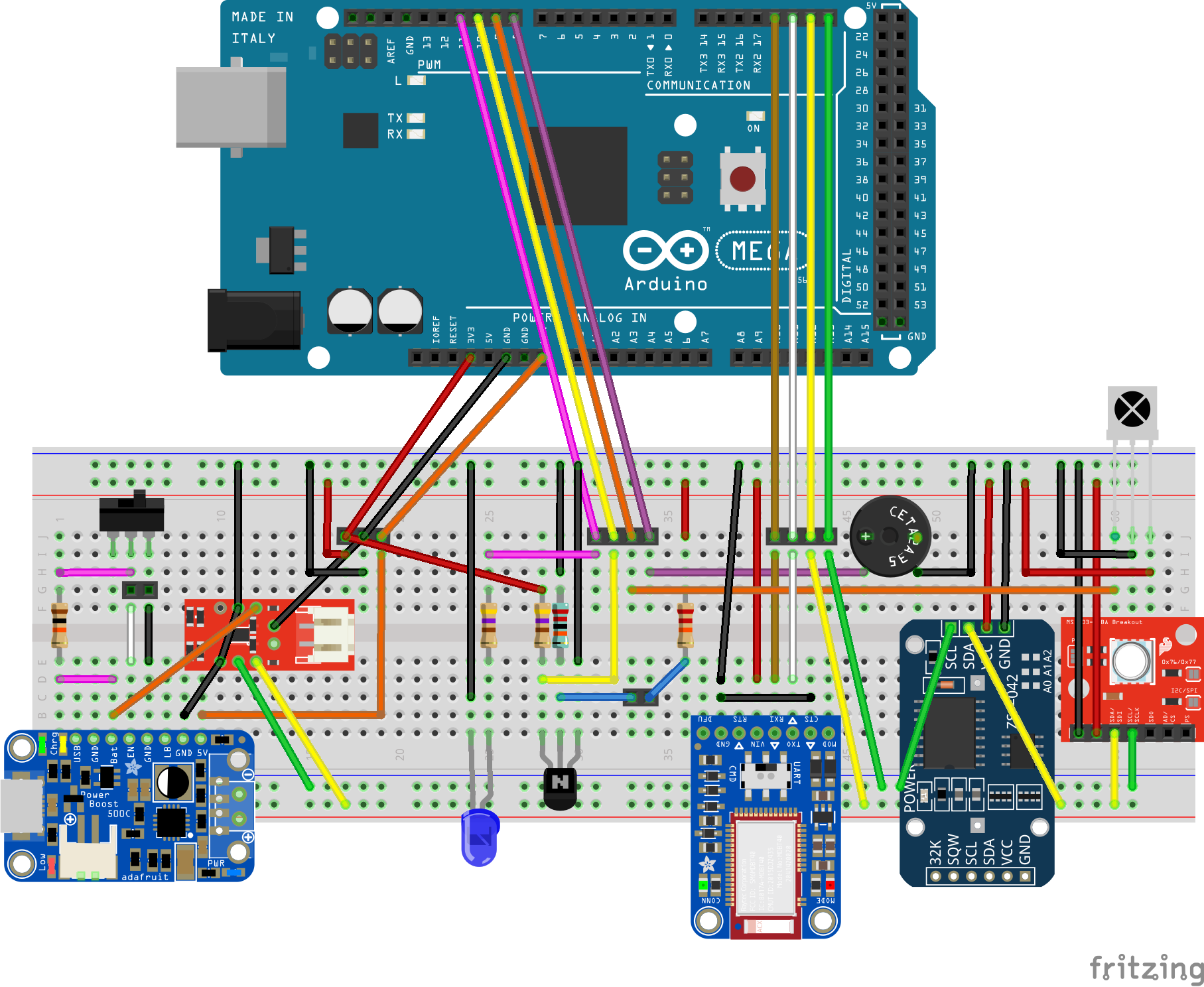
Full breadboard view
This diagram displays all parts plugged into a full sized solderless breadboard, wired together and connected to the Arduino Mega 2560 microcontroller board.
Please note that the TFT LCD display module is not part of this setup. It has to be plugged into the Arduino Mega board from the top side.

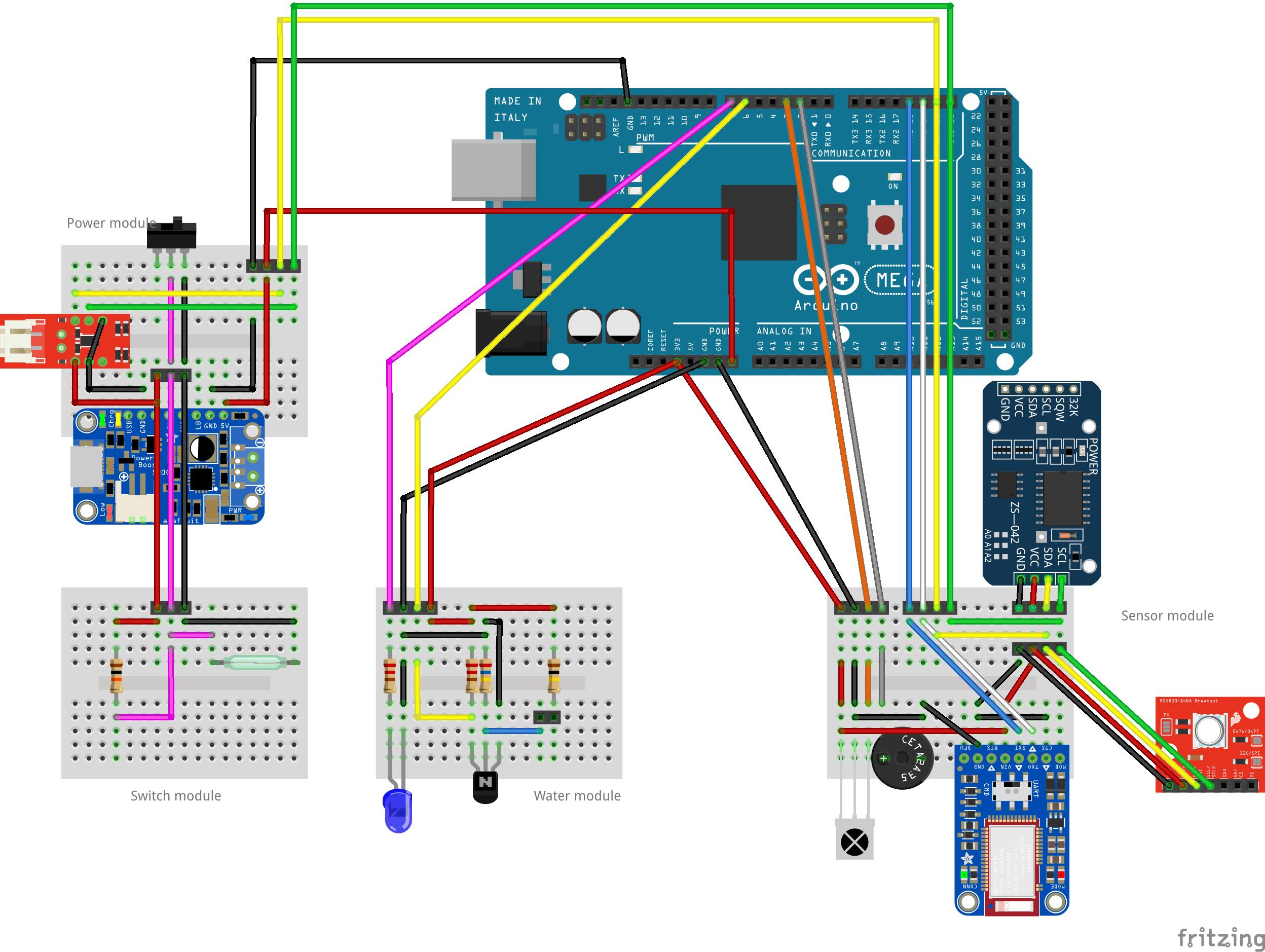
Modules
The full sized breadboard is good for initial testing, but it can’t be squeezed into the Otterbox Pursuit 40 waterproof case. A good idea is to break up the components into functional modules. I have identified the following ones:
- Power Module - these parts provide the power to DiveIno
- Switch Module - can turn on and off DiveIno
- Water Module - be able to detect, if DiveIno is in the water
- Sensor Module - provides time, pressure and Bluetooth communication capabilities

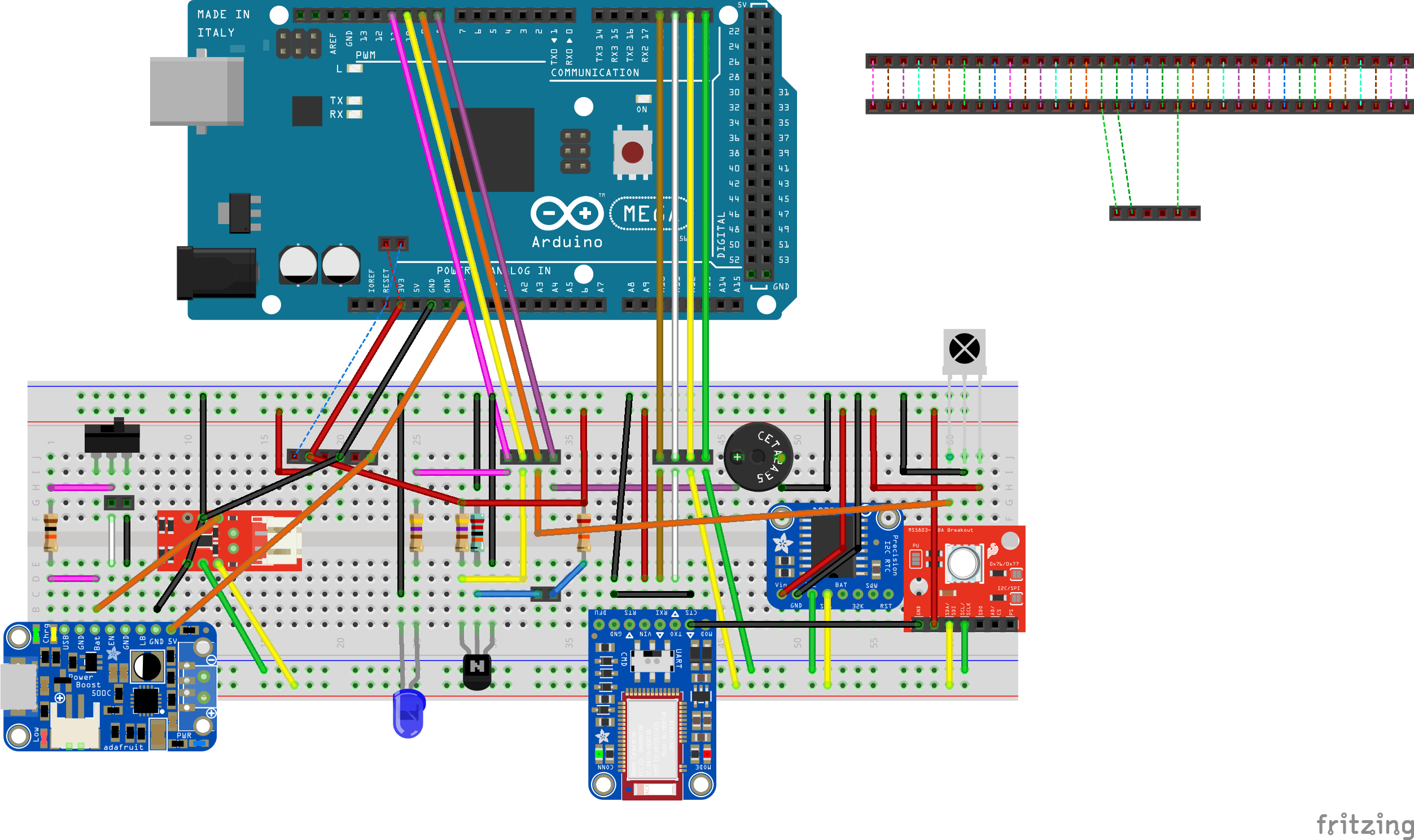
Shield version
When you plug in the display module into the Arduino Mega board the 3V3 power pin collides with the VCC power cable. You have the following options to overcome this limitation:
- Solder a pin onto the LCD and plug the power cable into it
- Solder a cable into the bottom side of the Arduino Mega board pin
- Create a shield, which plugs in between the Arduino Mega board and the display module
Obviously the first two points are quite easy to do, but the third one seems to be a better solution.

You might notice that in this case a different Real Time Clock module was used. The Adafruit DS3231 Precision RTC Breakout provides a much more space efficient option instead of the cheap DS3231 RTC module from China.

