DiveIno parts
In the Dive computer parts post I described the common parts of a regular dive computer. The challenge is about how to substitute these proprietary parts with off the market componets, which one can buy directly from the Internet.
DiveIno has the following three modules. I will discuss these modules in more details later:
- Screen and microcontroller
- Sensor module
- Power module
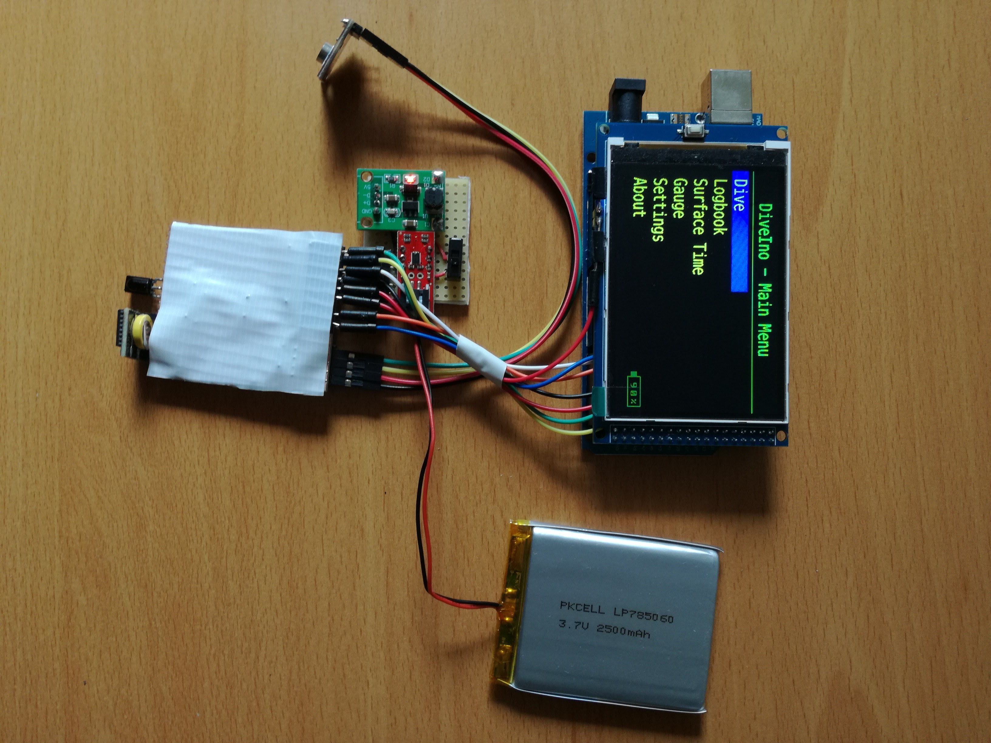
Screen and microcontroller
This module consists of an LCD screen and an Arduino Mega 2560 microcontroller board. You can buy these together from Deal Extreme.
The screen is a really bright color TFT IPS LCD screen. The resolution is quite high - 480x320 pixel. It snaps nicely on top of the microcontroller board.
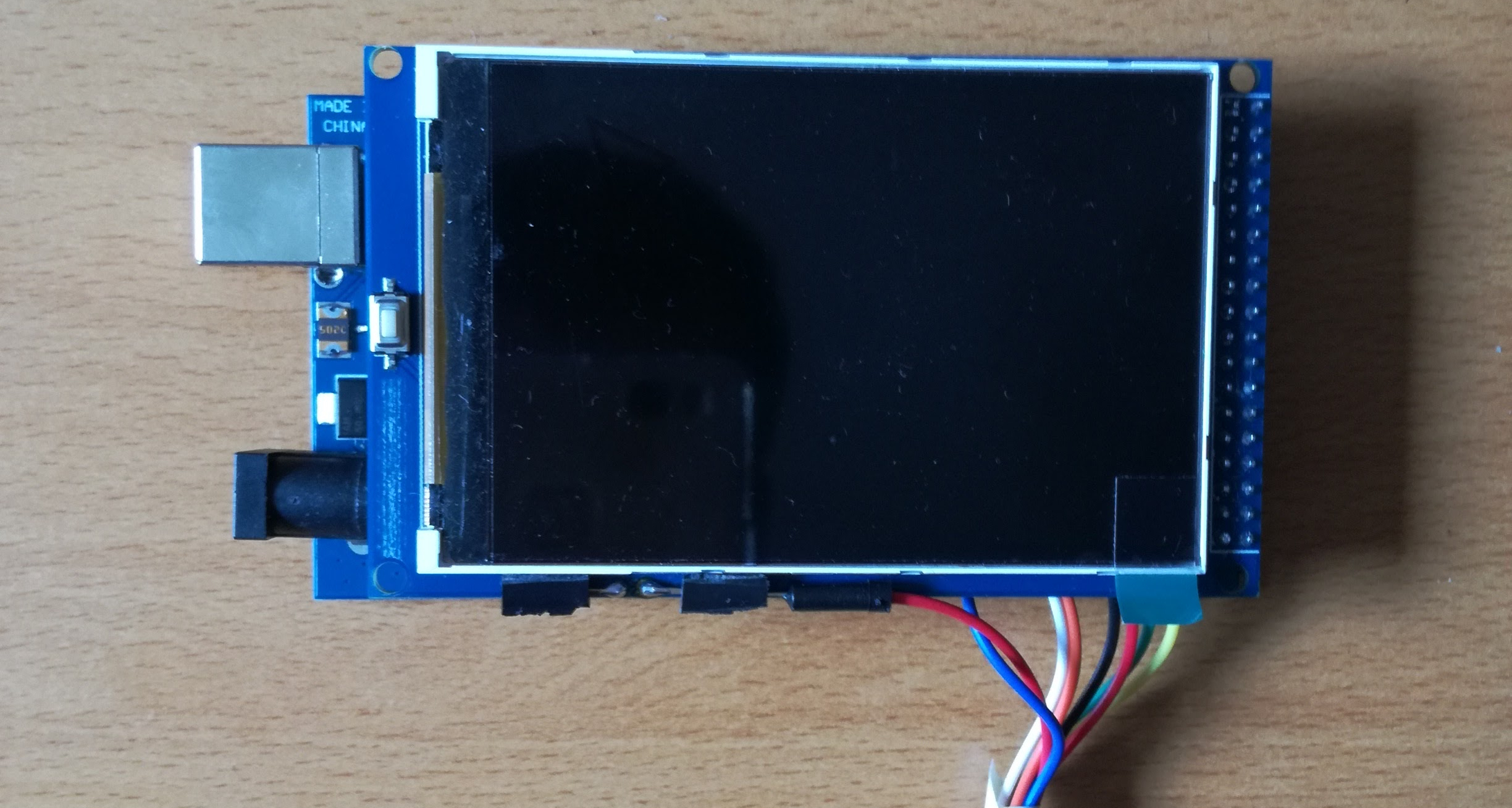
The manufacturer added an SD card slot to the back of the LCD circuit board, which comes really handy to store dive information and software settings.
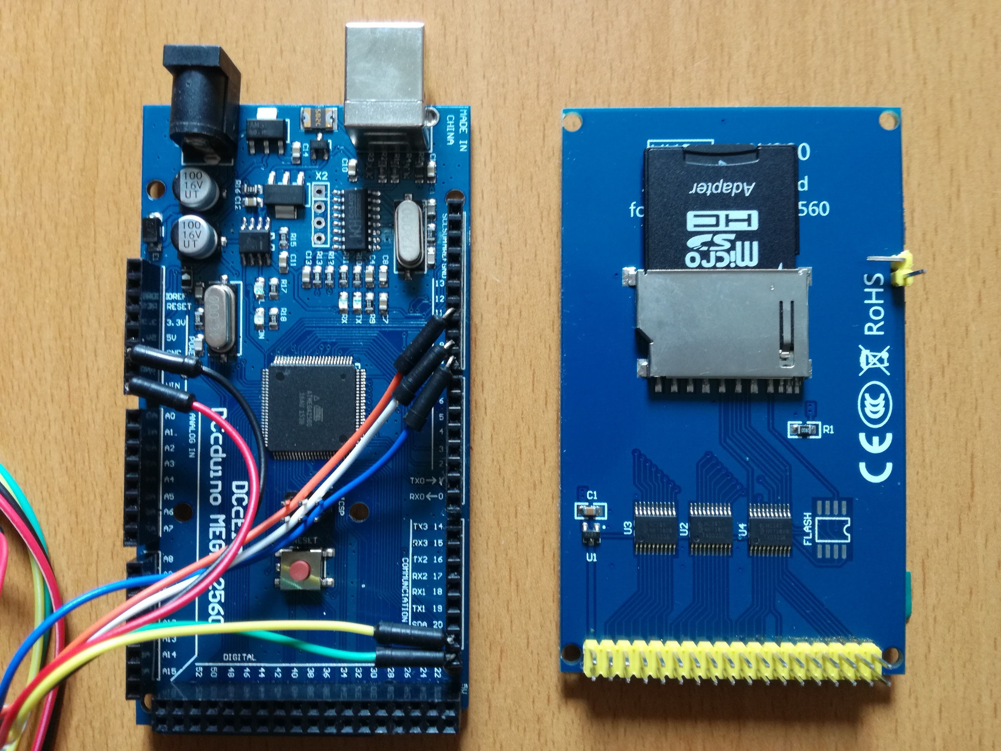
The microcontroller board is Arduino Mega 2560, which has enough processing speed and programmable memory.
Sensor module
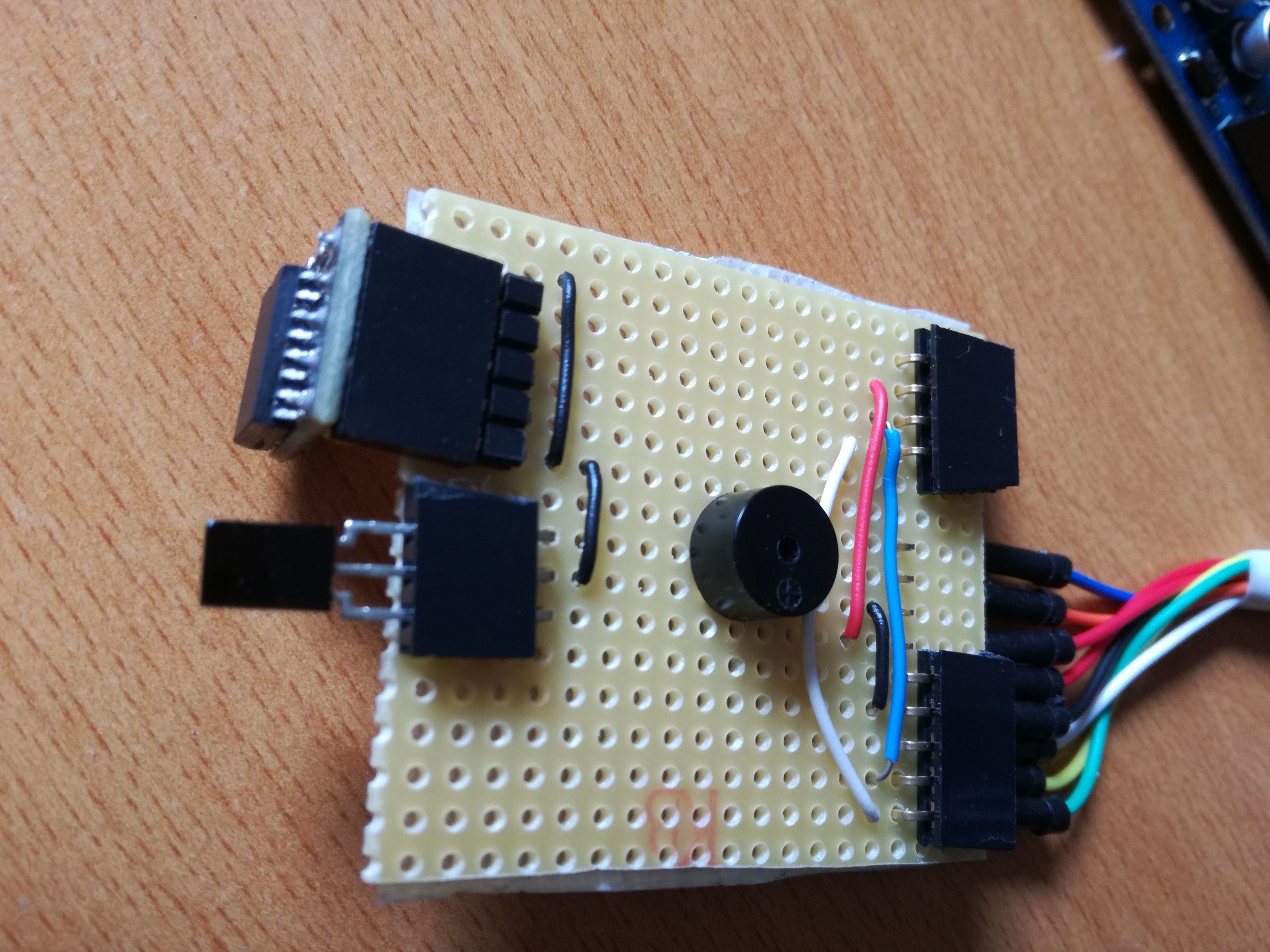
The main purpose of this module is to sense and to communicate with the surrounding environment. The following components constitute this module:
- Pressure Sensor
- InfraRed (IR) Receiver
- Piezo Buzzer
- Real Time Clock module
I use the SparkFun Pressure Sensor Breakout, but a cheaper Chinese clone is available on Ebay from gadgetextreme. Both breakout boards use the same MS5803-14BA pressure sensor, which is ideal to build a dive computer.
The Real Time Clock module is essential for tracking the exact date of the dive. I use the DS3231 RTC Module, which has a battery holder, so it keeps the preconfigured time, if you turn off the dive computer power supply. It is also really small.
In order to generate sound notifications, there is a need for a buzzer. I use a small passive piezo buzzer from my Arduino starter kit, but you can purchase one separately. For instance the cheap Adafruit Piezo Buzzer or the Deal Extreme Buzzer Module can be useful. Alternatively you can buy one in your local electronics store.
The Infrared Receiver Sensor is also essential, because the dive computer will be remote controlled through this sensor. I use the Adafruit TSOP38238 IR Sensor, but any 38KHz 3.3V or 5V compatible sensor can be used.
Power module
The power module has to provide power to the dive computer from a LiPo battery. It has the following parts:
- Power Switch
- Fuel Gauge
- DC to DC Booster
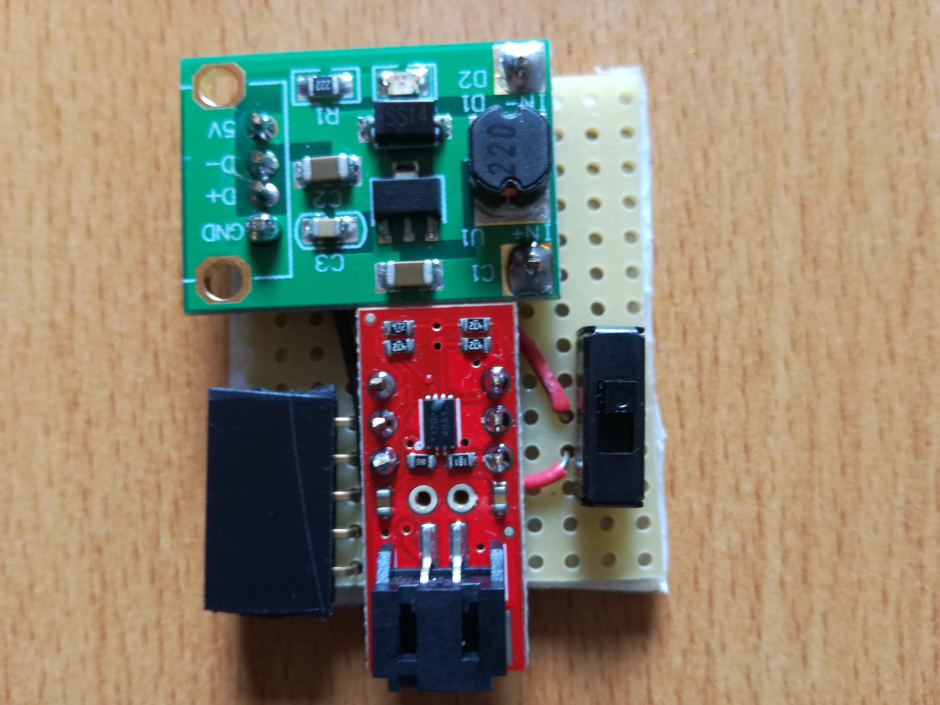
The usage of the Power Switch is self explanatory. We have to turn on and off the power. An SPDT (Single Pole Double Throw) version has to be used. I use the Breadboard-friendly SPDT Slide Switch from Adafruit, but the Sparkfun SPDT Mini Power Switch can be used as well.
The computer will display the current battery charge percentage in order to inform the diver about the remaining juice. The SparkFun LiPo Fuel Gauge connects the attached LiPo battery to the computer and at the same time it measures its charge level.
The Arduino Mega 2560 microcontroller board works on 5V, but the LiPo battery can provide only 3.7V, so a booster circuit has to be used. I use the DC-DC Converter Booster Module for this purpose, which is quite effective and stable.
Extras
Besides these three modules the following extra parts are needed:
- IR Remote Control
- LiPo Battery
- LiPo Charger
- SD Card
- Wires
- DuPont jumper wires
- Stripboard
- Header pins
For the IR Remote Control, there are many options available:
The last one even comes with an IR Receiver Module.
The capacity of the LiPo battery matters the most. I recommend something around 2000 mAh, which has enough juice to survive a long dive plus the surface transportation time to and from the dive site. Here are the options:
- Adafruit Lithium Ion Battery - 3.7v 2000mAh
- Adafruit Lithium Ion Polymer Battery - 3.7v 2500mAh
- Sparkfun Polymer Lithium Ion Battery - 2000mAh
I suggest to buy two LiPo batteries and replace them with each other after the dive. You can charge one while the other is in operation. You will need a LiPo charger for your batteries. I use the SparkFun LiPo Charger Basic, which is small, cheap and quite handy.
You will need an SD card to be able to store dive logs and device settings. The capacity can be anything, because the dive log files don’t consume too much disk space. You can use the Kingston SDC4/8GB 8GB microSDHC Class 4 Memory Card with Adapter.
You will need wires to be able to connect the various parts with each other. You can use Breadboard Jumper Wires in order to connect the Arduino microcontroller board with the various other modules. Solid core wires is advised to use to build electrical connection between the module parts. I use the Hook-up Wire Spool Set from Adafruit, which is quite handy and colorful!
Most likely you will also need some Male to Female DuPont Breadboard Jumper Wires.
I used various Stripboards as the solderable prototype boards for the modules. I purchased these in the local electronic parts store. I use two types, the one with Continuous strips and a TriPad version.
You will also need male and female header pins. You can buy these in your local electronic parts store, but of course you can buy them online: Straight Male Headers and Straight Female Headers.
Waterproof case
Besides the previously mentioned parts for sure you will need a waterproof dry case in order to bring your fully assembled hardware under the water. The case has to be transparent in order to be able to see the screen of the computer and can withstand about 4-5 bar water pressure.
I use a clear Otterbox Pursuit 40 case, which can withstand about 30 meter (100 feet) water pressure. It provides enough space for the dive computer parts.
This can be purchased on Ebay for about $25.

